SOLIDWORKS For beginner Introduction #qselects
- Arulsha

- Mar 18, 2020
- 2 min read
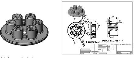
The Introduction to SOLIDWORKS lesson guides you through the creation of a part and a drawing. You create this part and drawing:

This lesson includes:
Creating base, boss, and cut features from sketches
Adding fillets to smooth edges
Creating a circular pattern
Adding drawing views
Adding centerlines,
center marks, and dimensions to the drawing
For your first part, you create the pressure plate shown below. Apart is a 3D model made up of features.

Click New

on the Standard toolbar. The New SOLIDWORKS Document dialog box appears.
2, click part
3, click ok
A new part window appears.
When toolbar buttons have an orange border, for example, you can click them in the tutorial window to flash the corresponding button in the SOLIDWORKS window.
Sketching the Circle
The first feature in the part is a cylinder extruded from a sketched circular profile.
Click Extruded Boss/Base 📷 on the Features toolbar. The Front, Top, and Right planes appear in the graphics area.
Move the pointer over the Top plane to highlight it, then click to select it. The display changes so that the Top plane is facing you. A sketch opens on the Top plane.
Click Circle 📷 on the Sketch toolbar. The Circle PropertyManager opens in the left pane.
Move the pointer over the origin
The pointer changes to 📷. This indicates a coincident relation between the center of the circle and the origin.
Click to place the center point on the origin.
Move the mouse and notice a preview of the circle dynamically follows the pointer.
Click to finish the circle and click 📷 in the PropertyManager.
The size of your sketch entities does not need to be exact. For example, this circle does not need to be 61.3mm. You later add dimensions to specify the size of the sketch entities.

Adding Dimensions
Click Smart Dimension 📷 (Dimensions/Relations toolbar).
Select the circle. Notice the preview of the diameter dimension.
Move the pointer to where you want the dimension and click to add the dimension.
In the Modify box, type 128, then click 📷 and click in the graphics area.

Extruding the Base Feature
Extrude the 2D sketch to create the 3D cylinder.
Click Exit Sketch 📷 on the Sketch toolbar. You exit the sketch when you are done with the 2D profile and are ready to create the 3D cylinder. The settings for the extrusion appear in the PropertyManager in the left panel.
In the PropertyManager, under Direction
1:Select Blind in End Condition.
2 Set Depth 📷 to 7.Notice the shaded preview of the extrusion.

3, Click 📷. The first feature is complete. Boss- Extrude1 appears in the FeatureManager design tree in the left panel.
Saving the Part,
Click Save 📷 on the Standard toolbar.
In the dialog box, type Pressure Plate for Filename.
Click Save. The extension .sldprt is added to the file name, and the file is saved.
SKETCHING THE BOSS


Comments